Certification test guide (CE / UL)
How to prepare and run the safety and EMC tests of a power supply on your bench, what connects to what, with which instrument and which values, before taking it to a lab.
1. What a pre-compliance test is
Repeating on your bench, with your instruments, the tests the lab will run, so you arrive knowing the design passes. It saves lab rounds (weeks and money each) and lets you fix problems early: a short clearance, a Y capacitor with too much leakage, a transformer running hotter than expected, a mains filter that falls short.
Well-documented tests (calibrated instruments, procedure and results) also go into the technical file for CE marking, which in many cases you can do yourself (see section 2).
2. CE and UL: how they work
| CE (European Union) | UL / cUL (USA and Canada) | |
|---|---|---|
| Who grants it | The manufacturer: self-declaration of conformity (non-medical supplies). | A recognised lab (NRTL): UL, Intertek (ETL), CSA, TÜV SÜD/Rheinland… |
| Directives / requirements | Low Voltage 2014/35/EU (safety), EMC 2014/30/EU, RoHS 2011/65/EU; external supplies: ecodesign (Regulation (EU) 2019/1782). Medical: Regulation (EU) 2017/745 (with a notified body depending on class). | The equivalent UL/CSA standard (UL 62368-1, UL 61010-1, UL 60335-1, ANSI/AAMI ES60601-1). EMC: FCC part 15 (USA), ICES-003 (Canada). |
| What you do | Tests (your own or in a lab), technical file, EU declaration of conformity, CE marking. | Send samples and documents to the NRTL; they test and then inspect the factory periodically. |
| What this guide is for | You can run and document the tests yourself. | Getting to the NRTL with no surprises. |
The CB scheme (IECEE) lets one IEC test report serve many countries — usually the most efficient route if you sell outside the EU. With a CB report, the NRTL for UL only adds the national differences.
3. Which standard applies
| Standard | For which equipment | Examples |
|---|---|---|
| IEC/EN/UL 62368-1 | Audio/video, IT and communication equipment and their supplies (including external ones). | PC supplies, adapters, network equipment supplies. |
| IEC/EN/UL 61010-1 | Measurement, control and laboratory equipment. | Lab supplies, supplies for instruments or research equipment (e.g. quantum computing). |
| IEC/EN 60335-1 (+ the appliance's part 2) | Household and similar appliances. | Supply built into a household appliance. |
| IEC/EN 60601-1 (+ 60601-1-2 EMC) | Medical electrical equipment. | Medical supplies (2 MOPP). |
The standard is set by the end equipment the supply goes into, not by the supply. A supply sold on its own usually follows 62368-1. IEC 61204-7 (safety of low-voltage switch-mode supplies) also exists for industrial supplies.
4. Equipment: what you have and what you'd need
| Test | Equipment | Status |
|---|---|---|
| AC/DC hipot, insulation, earth, leakage | Associated Research Omnia 8106 (5 kV AC/DC, IR, 40 A, leakage with measuring networks) | You have it |
| Ground bond (alternative) | Hioki 3157 (up to 31 A AC) | You have it |
| Supply at extreme voltages | Chroma 61602 (programmable AC source) | You have it |
| Input power and current | Hioki 3332 (power meter) | You have it |
| Output load | Chroma 63600, Kikusui PLZ-72W | You have them |
| Temperatures | 34970A / Keithley 2700 with type K thermocouples | You have them |
| Conducted emissions | 50 Ω/50 µH LISN (TekBox TBLC08, R&S HM6050-2), 10 dB limiter, spectrum analyzer with 9 kHz RBW (your HP 3585A will do; or Siglent SSA3032X Plus with EMI option, Rigol DSA815-EMI), ground plane (1×2 m sheet) | Needed |
| Harmonics (pre-compliance) | Chroma 61602 + oscilloscope with current probe or clamp + Hioki 3332 | You have it (except the current probe if you don't have one) |
| Formal harmonics and flicker (61000-3-2/-3-3) | Power analyzer with IEC 61000-4-7 (Hioki PW3336/PW3390, Chroma 66202) and a clean AC source; for flicker, a 61000-4-15 function | Needed |
| Humidity preconditioning | Climatic chamber (40 °C, 93 % RH) — or have the lab do it | Needed |
| Accessibility | IEC 61032 test finger (probe B), 2.5 mm probe | Needed |
| Distances | Caliper and gauges; 1 mm strip for creepage (grooves) | You probably have them |
| Simulated faults | Cotton cheesecloth, tissue paper, heavy wire for shorts, gloves and goggles | Cheap materials |
| Immunity (ESD, bursts, surges) | ESD gun, EFT/surge generator — normally done in a lab | Lab |
| Radiated emissions | Near-field probes (to compare and locate); the real measurement in the lab's chamber | Lab |
5. Safety in the test area
- Fenced area (tape or screen), insulating mat, nobody else inside while voltage is on. One person operates the tester.
- Wire the Omnia interlock (rear connector) to the door/screen: without it closed, no high voltage comes out.
- HV leads in good condition, insulated clips; RETURN always connected before HV.
- After DC hipot or insulation tests the EUT is left charged: wait for the Omnia to finish discharging.
- Fault tests: goggles, gloves, CO₂ extinguisher at hand, EUT inside a metal box or on a non-flammable surface.
- Power the EUT from the AC source (isolated from mains) or through an isolation transformer when probing with the scope.
- OSA Lab asks you to confirm these conditions before each high-voltage or high-current test, and in Tools → Protections you can add rules (e.g. maximum temperature → turn off all outputs).
6. Working in OSA Lab
- Connect the instruments (the Omnia via RS-232 with the "Associated Research Omnia" profile, or GPIB) and open Tools → Certification tests.
- Fill in the equipment data (rated voltages, current and power, class I/II, circuit protection, maximum ambient temperature…) and choose the standard. Press Generate the test plan: you get the list with that standard's typical values.
- For each test: Connection and procedure tab (diagram and instructions), Parameters and limits (review and change them if your case requires), Run (choose the instruments and start) and Result (table, PASS/FAIL, remarks, photos).
- Manual tests (marking, distances, faults) are marked by hand with their remarks and photos.
- Equipment and laboratory… collects the instruments with serial number and calibration date (for the technical file).
- Save the project (
.osacert) and create the PDF report: summary, equipment data, instruments used and each test with its diagram, parameters, measurements and remarks.
7. Values by standard
Typical values for 230 V (250 V working). Those marked * must be checked against the standard's table for your case.
| Test | 62368-1 | 61010-1 | 60335-1 | 60601-1 |
|---|---|---|---|---|
| Basic hipot (primary–earth) | 1500 Vac* 60 s | ≈1390 Vac 5 s* (proposed 1500 Vac 60 s) | 1250 Vac 60 s | 1 MOOP 1500 Vac 60 s |
| Reinforced hipot (primary–secondary) | 3000 Vac (4242 Vdc) 60 s* | ≈2210 Vac 5 s* (proposed 3000 Vac 60 s) | 3000 Vac 60 s | 2 MOPP 4000 Vac 60 s |
| Protective earth | 2 × protection (32 A), 120 s, ≤ 0.1 Ω | 25 A, 60 s, ≤ 0.1 Ω | max(25 A; 1.5·In), ≤ 0.1 Ω | max(25 A; 1.5·In), 5–10 s, ≤ 0.1 Ω (0.2 with cord) |
| Touch / leakage (normal) | 0.5 mA | 0.5 mA | 0.25 mA (cl. II) / 0.75 mA (cl. I portable) | touch 100 µA, earth 5 mA |
| Touch / leakage (single fault) | 3.5 mA* (cl. I, open earth) | 3.5 mA | — | touch 500 µA, earth 10 mA |
| Supply for leakage | 1.1 × Vmax | 1.1 × Vmax | 1.06 × Vnom | 1.1 × Vmax |
| Input | ≤ rating + 10 % | ≤ rating + 10 % | tables 1/2 (≈ +15 %)* | ≤ rating + 10 % |
| Heating (surfaces) | TS1: 48 °C (>1 min)* | metal enclosure 65 / plastic 85 °C | as rise (K)* | 48 °C (>1 min), applied part 43 °C |
| Conducted EMC | EN 55032 class B | EN 55011 (EN 61326-1) | EN 55014-1 | CISPR 11 (60601-1-2) |
DC equivalent for hipot: Vdc = 1.414 × Vac. With large Y capacitors, DC avoids trips caused by capacitive current.
8. Input current / power
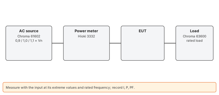
- Chroma 61602 → Hioki 3332 → EUT → Chroma 63600 load at rated output load.
- Measure at the minimum, nominal and maximum rated voltage, at rated frequency, at steady state (wait a few minutes).
- Pass if current and power do not exceed the marking by more than the standard's percentage. Also record the power factor.
9. Protective earth continuity
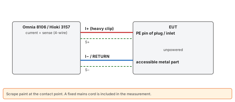
- Class I only. EUT unpowered. 4-wire measurement: current and sense clips on the PE pin of the plug or IEC inlet.
- The other pair on each accessible metal part that must be earthed (scrape the paint, or use the screws).
- With a fixed cord, measure from the plug pin (the cord counts in the resistance).
10. Electric strength (hipot)
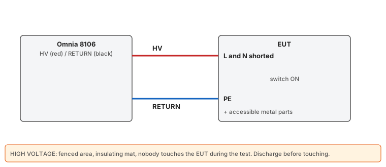
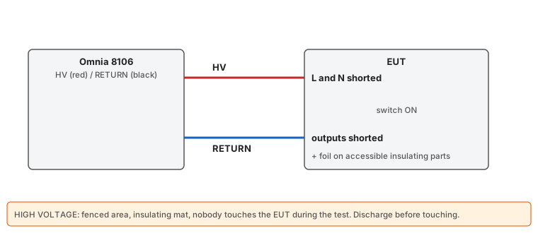
- First, the humidity preconditioning if the standard requires it (type test: 40 °C and 93 % RH, 48 h; 120 h for tropical climates). Without a chamber, run the test anyway and note it: it is a good indicator, but the lab will do it after humidity.
- Primary–earth (basic insulation): L and N shorted to HV; PE and accessible metal to RETURN.
- Primary–secondary (reinforced/double): L and N shorted to HV; all outputs shorted together to RETURN (and PE for class I, unless you test the earth insulation separately).
- Gradual ramp (not a step), full duration, ramp down. Pass if there is no breakdown (disruptive discharge). The Omnia current limit is only there to detect breakdown: set it above the normal capacitive current (in AC, Y caps give a few mA).
- Components to earth (Y caps, varistors, arresters) may be disconnected for the type test if the standard allows: note it.
11. Insulation resistance
Same connection as primary–earth hipot, 500 Vdc. Not a general requirement in 62368-1 or 61010-1; it was in older editions of 60335-1 (2 MΩ basic / 7 MΩ reinforced). Useful as a preliminary check (it detects moisture or contamination) and in production.
12. Touch and leakage current
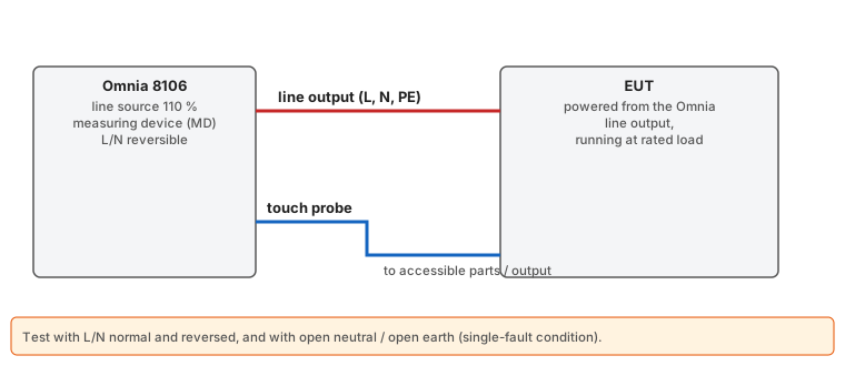
- The Omnia 8106 powers the EUT from its line output and measures with the standard's network (IEC 60990 fig. 4 for 62368/61010/60335; the 60601 MD for medical equipment).
- The test voltage is the Omnia's mains input voltage: to test at 1.1 × Vmax (264 V), feed the Omnia from the Chroma 61602 at that voltage. OSA Lab does it automatically if you choose the AC source in the test.
- EUT running at its load. Probe on each accessible part (and on the outputs if accessible). Earth leakage (60601): current in the PE.
- Repeat with L/N reversed and under single fault (open earth, open neutral) with their limits.
13. Heating
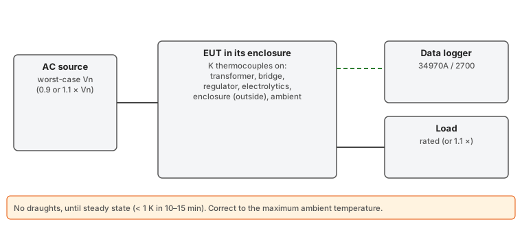
- Fine-wire K thermocouples bonded with Kapton tape or thermal adhesive on: transformer winding and core, bridge rectifier, regulators/MOSFETs, output diodes, electrolytics (their life depends on it), terminals, enclosure outside (where touched) and one in ambient air.
- EUT in its final enclosure, in its use position, without draughts (a cardboard box around it helps). For 60335-1: black-painted plywood test corner.
- Worst-case voltage (0.9 or 1.1 × nominal: whichever heats more; for linear supplies with a transformer it is usually 1.1 ×) and rated load.
- Until steady state: less than 1 K change in 10–15 min (several hours with large transformers).
- Correction to maximum ambient:
T = T measured − T ambient + T amb. max.(in 60335-1 the limits are rises in K). - Limits: each component's own (electrolytics 105 °C, transformer insulation by class, FR-4 board ~130 °C…) and the standard's accessible surface limits.
14. Simulated faults
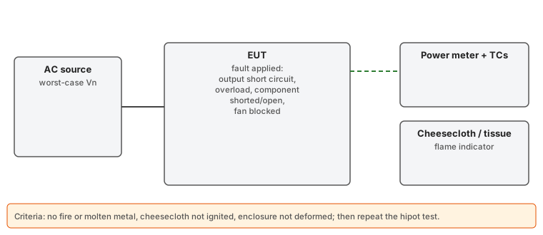
- Output short circuit (heavy wire or load in short mode), overload (just below the protection trip), blocked ventilation, components shorted/open (one at a time, those that could cause a hazard), transformer overload.
- EUT on tissue paper and covered with cotton cheesecloth. Record input power and temperatures until a protection operates or it stabilises.
- Pass if: no fire or molten metal outside, cheesecloth not ignited, enclosure not deformed exposing hazardous parts, and then repeat the hipot of the affected insulation.
15. EMC: conducted emissions (pre-scan)
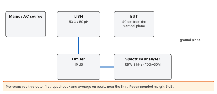
- Ground plane (sheet) on the floor or table; LISN bolted to the plane with a short, wide strap. EUT on a non-conductive table 80 cm above the horizontal plane or 40 cm from a vertical one; LISN 80 cm from the EUT; excess cable folded in a 30–40 cm zigzag.
- LISNs have large capacitors to earth: feed through an isolation transformer (or the AC source) so the RCD does not trip.
- LISN RF output → 10 dB limiter → analyzer. Never without the limiter when switching the EUT on or off.
- Sweep 150 kHz – 30 MHz, 9 kHz RBW, peak detector, on L and N. First with the EUT off (ambient).
- Correction: reading + LISN loss + limiter attenuation (enter it in the test's "Correction").
- If the peak is below the average limit with margin (6 dB): pass. Otherwise, measure those peaks with quasi-peak and average. With an analyzer with CISPR detectors (Agilent E7401A–E7405A) OSA Lab does it for you: it measures each peak in zero span with quasi-peak and average and gives the result. With the HP 3585A, set up the front panel (30 kHz RBW) and check doubtful peaks by hand.
Limits (dBµV): EN 55032 class B — QP 66→56 (150–500 kHz, linear in log f), 56 (0.5–5 MHz), 60 (5–30 MHz); AVG 56→46, 46, 50. Class A — QP 79 / 73, AVG 66 / 60. EN 55014-1 — QP as class B, AVG 59→46, 46, 50.
16. Other requirements
- Full EMC: besides conducted, radiated (chamber), harmonics (61000-3-2, equipment > 75 W) and flicker (61000-3-3), and immunity (ESD 61000-4-2, radiated -4-3, bursts -4-4, surges -4-5, conducted -4-6, dips -4-11). Normally in a lab.
- RoHS: declarations from each component supplier (or XRF analysis).
- Ecodesign for external power supplies (Regulation (EU) 2019/1782): see below.
Current harmonics (EN 61000-3-2, pre-compliance)
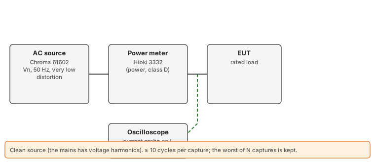
- Supply the EUT from the Chroma 61602 at rated voltage: the mains has voltage harmonics that skew the measurement.
- Current probe or clamp on the line conductor, to the oscilloscope. Enter its factor in "Current probe (A/V)" (100 mV/A → 10).
- EUT at rated load. OSA Lab takes N captures of 10 cycles, computes each harmonic (FFT over an integer number of cycles, as in IEC 61000-4-7) and keeps the worst.
- Class A: absolute limits (2.30 A for the 3rd, 1.14 A for the 5th…). Class D (PCs, monitors and TVs up to 600 W): mA/W with the power measured by the Hioki 3332. Up to 75 W there are no limits (except lighting).
- It is indicative: the formal test uses an IEC 61000-4-7 analyzer with a reference source.
External power supply ecodesign (Regulation (EU) 2019/1782)
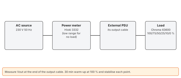
- Only for external supplies (adapters and chargers) up to 250 W. It is disabled in the plan: enable it if it applies and enter the rated output voltage and current and the type (basic, low voltage < 6 V, multiple output or AC-AC).
- 230 V 50 Hz from the Chroma 61602; Hioki 3332 power meter at the input; load at the output, measuring at the end of the output cable.
- 30 min at 100 % load, then 100, 75, 50, 25 and 10 % and no load, waiting for each point to stabilise.
- Average efficiency (25–100 %) and at 10 %, and no-load power (≤ 0.10 W up to 49 W, 0.21 W above), compared with annex I. Check the values against the current text of the regulation.
17. Technical file and declaration of conformity (CE)
- Product description, schematics, list of critical components (with their certificates: transformer, optocouplers, Y caps, fuses, connectors, plastics with their flammability class).
- Risk analysis, test reports (the OSA Lab PDFs, with instruments and calibrations), manual and safety instructions, labels.
- EU declaration of conformity: manufacturer, product, directives, harmonised standards with their year, place, date and signature.
- Keep it for 10 years after the last unit is placed on the market.
© 2026 OSA Electronics · OSA Lab